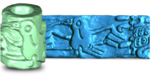
Geomagic Wrap scan-to-CAD software delivers the fastest, most accurate path from 3D scanned point clouds to 3D polygonal meshes and surface/solid models that you can use instantly in downstream applications.
| Technology | Scan-to-CAD |
| Manufacturer | Oqton | Geomagic |
| Licence types | Online, Dongle, Network |
| Attributes | Polygon mesh editing, surfaces to solids |
Geomagic Wrap delivers the fastest, most accurate path from point clouds to 3D polygon meshes and surface/solid models that you can use instantly in downstream engineering, manufacturing, art, industrial design and more. As part of your 3D digital thread, Geomagic Wrap provides the digital bridge from scan-to-CAD for creating perfect data to use directly in 3D printing, milling, archiving, and other 3D uses.
With advanced and exact surfacing tools, Geomagic Wrap delivers powerful, easy-to-use, cutting-edge modeling functions for that flawless 3D model. Scripting and macros also automate functions for repetitive tasks during the reverse-engineering process.
Geomagic Wrap enables you to transform point cloud data, probe data, and imported 3D formats like STL and OBJ into 3D polygon meshes for use in manufacturing, analysis, design, entertainment, and archeology.
Geomagic Wrap enables 3D imaging for analysis, animation, and filmmaking.
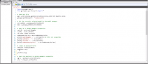
Execute custom scripts and macros and customize your workflow for unique applications with the scripting editor, which includes features for in-app scripting and macro creation and editing.
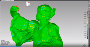
Measure and compare objects:
Texture manipulation tools streamline workflows involving color and texture. Create higher-quality, more logical texture maps for improved downstream usability.
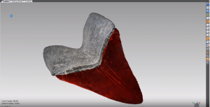
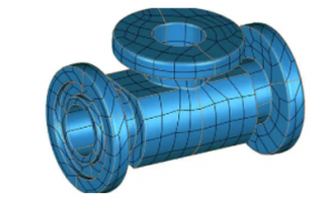
Use the Auto Surfacing feature to fit surface patches onto a mesh and create a surface body with the click of a button. This is important to design a complex, freeform part; create model data for manufacturing a freeform shape; or analySe a geometric shape.
Auto surfacing creates a surface body that can envelop the entire geometric shape of a target mesh. It provides two different methods:
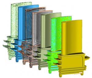
It creates a NURBS model with minimal user interaction. Its intelligent patch network tools include a choice of quad patch fitting and T-junction patches that automatically construct a 3D patch network on an entire mesh. And it creates continuous NURBS surfaces by fitting control points in the network. It is useful to:
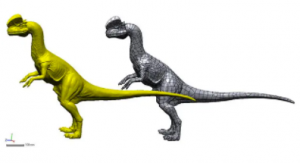
Scan directly into Geomagic Control X, Geomagic Design X, Geomagic for SOLIDWORKS, and Geomagic Wrap.
Construct polygon objects from point clouds—which is often a particularly challenging operation for scans that are missing information or are time intensive with large data sets—and create watertight meshes faster.
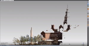
Use automated macros for scan processing and enhanced macro documentation to speed up your everyday workflows. Use macros to record, manipulate, and replay sequences of actions.
Inspired by Geomagic Control X inspection and metrology software, Geomagic Wrap includes fundamental measuring tools to quickly analyze scanned parts.
Cut cross-sections through your parts and extract and annotate angular, linear, and radial dimensions.
Extensive and precise Exact Surfacing tools provide you with more control over your surface quality and layout and enables total control over NURBS patch layout, surface quality, and continuity.
Extract a reference plane, vector, coordinate system, polyline, or point with multiple combinations of input. The reference geometry tools include various commands necessary for creating primitive geometries and editing the geometries.
In addition, you can export reference geometries.
Surface engraving can be difficult to represent visually on 3D-printed models. You can add alphanumeric and DFX-based labels underneath the part surface and then fill the trapped engraving with support material or a secondary part material during 3D printing to provide high contrast for greater visibility.
Expertly handle massive mesh and point cloud data alignment, processing, and refining mesh construction with point cloud processing tools.
Edit point clouds including:
Convert point clouds to/from other entities:
