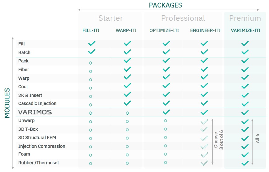
CADMOULD Engineer-it! plastic flow software enables you to quickly view results from simulating the filling of the injection moulding process and to see the effect of cooling, warping and more. Cadmould Engineer-it! includes Cadmould Warp-it! modules: Fill, Batch, Pack, Fiber, Warp, Cool, 2K & Insert, Cascadic Injection, VARIMOS process optimisation PLUS an extra choice of 3 modules from 6:-
Cadmould UNWRAP helps you to devise mold corrections for warpage compensation, in order to eliminate shrinkage and warpage. To achieve this, Unwarp uses the shrinkage and warpage results from the Warp module as inputs. The results that are computed include:
• Mold corrections for shrinkage compensation
• Mold corrections for warpage compensation
• Deformation corrections
• Deformed part geometries

Benefits
• Precise computation of mold compensation
• Maximum dimensional accuracy through optimal tooling
• 3D-print physical representations of deformed component geometries, to assess dimensional compliance and compatibility with connecting parts
• Better shrinkage and warpage results from the start, because they have been compensated for adequately. As a result, better first-time right ratio and reduction of costly tool corrections.
Figure 20: CADMOULD Unwarp displays the necessary mold compensation for shrinkage and warpage. The original part geometry is shown in grey. Orange areas signify compensated parts of the mold. The compensated mold can be exported in suitable CAD-compatible formats (tessellated, suitable for reverse engineering, see details below).
• The ultimate result: significant time and cost savings, and an enhanced ability to discuss options and their advantages and disadvantages with your customers and colleagues
Formats
You can view the results in CADMOULD, and export the computed warpage compensations, as well as deformed part geometries, for further use elsewhere. The following output formats4 are supported by our integrated export tool:
• STL (.stl)
• STEP (.stp / .step)
• IGES (.igs / .iges)
• Parasolid (.x_t / .xmt / .x_b / .xmt_txt)
• PRC (.prc)
• JT (.jt)
• UNIVERSAL3D (.u3d)
• VRML (.vrml)
• OBJEKT (.obj)
• COLLADA (.dae)
• Unwarp also enables you to create text files with displacement vectors, for example for working with CATIA® RSO®.
• In addition, it is also possible to view the geometries in HTML and 3D-PDF formats.
CADMOULD T-Box enables the thermal design of your mold. For this purpose, the
temperature control channels of the Cool module are combined with a complete
calculation of the heat transfer processes across the entire injection mold. T-Box
offers you two options:
1. By using an automatically generated mold sketch, consisting of temperature
control, gating system and part, T-Box can be used right from the beginning of
mold development
2. You can also use T-Box after completion of the mold design. In this case, T-Box
simulates with the main mold components

T-Box computes the following results in three-dimensional detail:
• Number of cycles until the thermally stable state of the mold is reached
• Local variation of cavity wall temperatures during the entire cycle
• Temperature distribution and heat flows in the mold sketch or the simulated
mold components
• Flow rate and pressure loss in the cooling system
• Temperature change of the tempering medium
• Turbulence of the flow
• Cooling efficiency
Benefits
• Determine cooling behavior for optimal cavity wall temperatures
• Determine cooling time
• Predict temperatures and heat flows in the mold
• Detect and eliminate hot spots due to use of different materials, mold
separation or hot runner influence
• Reduce warpage through optimized tool inserts
• Reduce cycle time through mold inserts adapted to the part and the process
• Optimize existing cooling systems
• Design molds with confidence, with a better first-time right rate and fewer
costly correction loops. Significant time and cost savings, and better
discussions.
CADMOULD Structural FEM enables the simulation of a part’s mechanical behavior,
taking into account fiber-related anisotropies. The Structural FEM module is thus an
ideal complement to the Fill (simulation of the filling), Pack (simulation of the holding
pressure and cooling phase) and Fiber (simulation of fiber orientation) modules. In
combination with the module 2K & Insert, the deformation of inserts or the core
offset during the injection phase can be simulated. The following results are
computed by the Structural FEM module:
• Deformation (displacement in space)
• Von Mises residual stress
• Elongation
• Strain energy density

Benefits
• Improve engineering results by anticipating mechanical component properties
• Select materials that are compatible with expected stress and load
• Analyze the influence of fiber orientation, wall thickness and ribs on the
mechanical properties of the part
• Analyze part stability and loads, once the part is built into a combined product
• Reduce mechanical stress on inserts, through optimized injection phase
• In combination with 2K & Insert: takes new thicknesses due to insert
deformation or core shift into account for the filling behavior
Results
Our specialized module for injection compression computes the core CADMOULD
results, in settings where injection compression procedures are applied:
• Filling
• Weld lines and air enclosures
• Pressure loss and distribution
• Temperatures
• Flow speeds
• Volume flow
• Clamping forces
• Stamping force and speed
• Shrinkage and warpage
The injection compression module builds on CADMOULD Fill (filling simulation), Pack (packing pressure and cooling phase) and Warp (shrinkage and warpage).

Benefits
• Optimally design of the injection compression molding process
• Optimize the filling and packing phase, taking into account the compression movement of the mold
• Compute and optimize stamping force and speed
• Determine the right pressure and clamping forces
• Optimize the stamping movement of the mold
Cadmould FOAM enables the simulation of foam injection molding. You can simulate all common chemical and physical foam injection molding processes, such as MuCell®, Cellmould® and Optifoam®. CADMOULD Foam computes the following results, for foam materials:
• Filling
• Density distribution in the part
• Bubble distribution and size
• Clamping forces
• Component weight
• Cooling times
• Weld lines and air inclusions
• Pressure distribution
• Temperatures
• Flow speeds
• Shrinkage and warpage
Foam builds on the following functionality from other modules: filling (Fill module), holding pressure and cooling phase (Pack module), and shrinkage and warpage (Warp module).
Distance from channel wall [%]
Bubble radius [mm]

Benefits
• Detect filling problems early on (air inclusions, weld lines, etc.), taking into account the influence of the foam on the viscosity
• Optimize propellant and gas / mass ratio
• Optimize part weight and density distribution
• Anticipate and fix shrinkage and warpage issues for foam projects
• Determine cycle times and clamping forces for foam projects
Cadmould RUBBER enables you to simulate elastomer injection molding. It computes the following results:
• Filling
• Weld lines
• Air inclusions and venting
• Pressure distribution
• Temperatures
• Shear rates
• Scorch
• Degree of cross-linking (also after demoulding)
• Heating time
• Shrinkage
• Warpage

CADMOULD Rubber is available in two forms. You can either acquire it standalone, or as a module that builds on and works best with the following other modules: Fill, Pack (holding pressure and cooling phase), Warp (shrinkage and warpage), Cool and T-Box (thermal mold design).